Hi, I am building a little 70's style analog computer, mainly for
learning purposes. For the most part I've been able to follow the
Grappendorf project schematics, but that project does not include
schematics for a comparator. I looked at the Anabrid THAT design
schematics, and I was going to make something based off that; however,
the Anabrid design uses Schmitt-Trigger inverters, which requires 5V
supply, and I was hoping not to have to mess around with 5V, everything
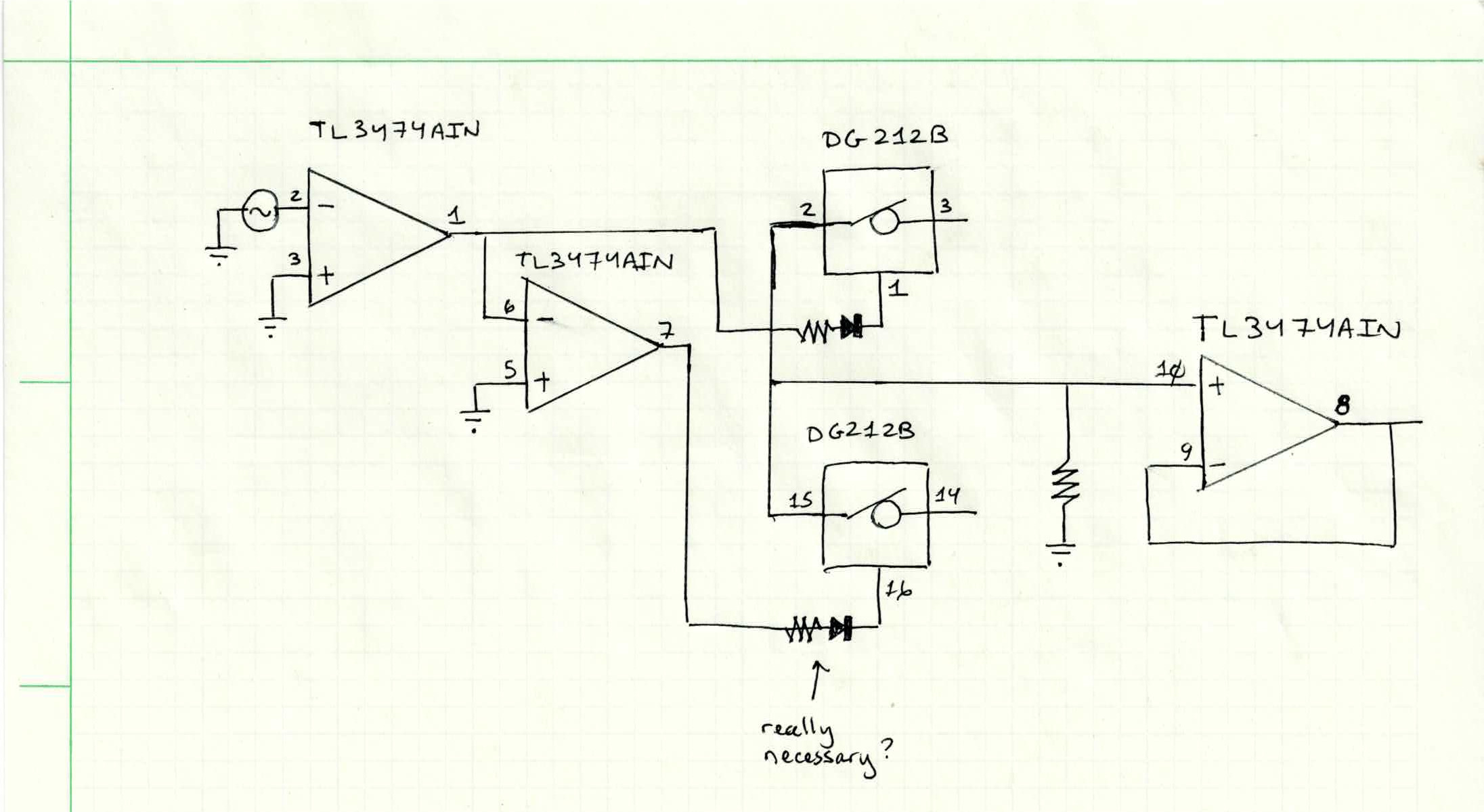
else in my system requiring only a +/- 15V. So, I was wondering if I
maybe I could get rid of the Schmitt-Trigger inverters from the design
and get by with just use op amps instead, like so:
http://gem.librehacker.com/gemlog/starlog/img/2025/20250425_comparator.jpg
But when I try to build this, I've seen various strange results from the switches, like it getting stuck with seemingly one switch stuck open and
one stuck close. I've done various bits of troubleshooting, but haven't
got to the bottom of it yet. Is there something fundamentally wrong with
the design?
Maybe the Schmitt-Triggers are critical for some reason...?
(Hysteresis?) I wonder if maybe I might have damaged the switches, so
that might be it, but I can't afford to order more right now.
--
Christopher Howard
"Christopher Howard" <christopher@librehacker.com> wrote in message news:87r01gqc76.fsf@librehacker.com...
Hi, I am building a little 70's style analog computer, mainly for
learning purposes. For the most part I've been able to follow the
Grappendorf project schematics, but that project does not include
schematics for a comparator. I looked at the Anabrid THAT design
schematics, and I was going to make something based off that; however,
the Anabrid design uses Schmitt-Trigger inverters, which requires 5V
supply, and I was hoping not to have to mess around with 5V, everything
else in my system requiring only a +/- 15V. So, I was wondering if I
maybe I could get rid of the Schmitt-Trigger inverters from the design
and get by with just use op amps instead, like so:
http://gem.librehacker.com/gemlog/starlog/img/2025/20250425_comparator.jpg >>
But when I try to build this, I've seen various strange results from the
switches, like it getting stuck with seemingly one switch stuck open and
one stuck close. I've done various bits of troubleshooting, but haven't
got to the bottom of it yet. Is there something fundamentally wrong with
the design?
I would avoid using op amps as comparators.
"Edward Rawde" <invalid@invalid.invalid> writes:
A more detailed schematic is needed, showing supply rail connections to the devices.
The op amps and switches are both +/- 15V supply.
The switches have a GND pin also.
--
Christopher Howard
Hi, I am building a little 70's style analog computer, mainly for
learning purposes. For the most part I've been able to follow the
Grappendorf project schematics, but that project does not include
schematics for a comparator. I looked at the Anabrid THAT design
schematics, and I was going to make something based off that; however,
the Anabrid design uses Schmitt-Trigger inverters, which requires 5V
supply, and I was hoping not to have to mess around with 5V, everything
else in my system requiring only a +/- 15V. So, I was wondering if I
maybe I could get rid of the Schmitt-Trigger inverters from the design
and get by with just use op amps instead, like so:
http://gem.librehacker.com/gemlog/starlog/img/2025/20250425_comparator.jpg
But when I try to build this, I've seen various strange results from the switches, like it getting stuck with seemingly one switch stuck open and
one stuck close. I've done various bits of troubleshooting, but haven't
got to the bottom of it yet. Is there something fundamentally wrong with
the design? Maybe the Schmitt-Triggers are critical for some reason...? (Hysteresis?) I wonder if maybe I might have damaged the switches, so
that might be it, but I can't afford to order more right now.
A more detailed schematic is needed, showing supply rail connections to the devices.
What's on pin 12 ?
"Edward Rawde" <invalid@invalid.invalid> writes:
What's on pin 12 ?
Pin 12 on the switches is for a logic power supply that was needed on
the "original manufacturer's products" but is not needed on the Maxim
chips.
--
Christopher Howard
| Sysop: | Keyop |
|---|---|
| Location: | Huddersfield, West Yorkshire, UK |
| Users: | 546 |
| Nodes: | 16 (2 / 14) |
| Uptime: | 150:15:25 |
| Calls: | 10,383 |
| Files: | 14,054 |
| Messages: | 6,417,787 |