XPost: uk.comp.homebuilt
On Wed, 1/8/2025 5:53 AM, fred wrote:
Andy Burns <usenet@andyburns.uk> wrote in news:lu4rgmFb19U1 @mid.individual.net:
Jeff Gaines wrote:
I removed the CMOS battery, there is no clear CMOS button, will have to
try and see if there's a clear CMOS jumper.
short the battery terminals while it is removed.
I'd be surprised if that worked as there's usually a series diode to
prevent reverse charging of the battery under fault conditions (or that's
the way it certainly used to be done).
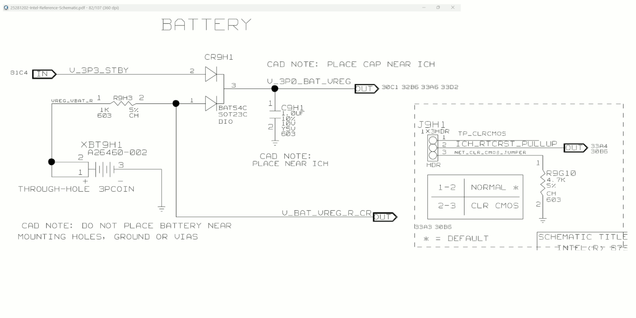
Note that Intel reference schematics are not known for their "realism"
and real circuits have slightly different details. For example, the
Port Angeles on this particular schematic is pure imagination and
not real (not a proper SuperIO). Still, you can use this little
circuit, to have a discussion about the Clear CMOS jumper and
what good (if any), shorting the battery terminal would have.
[Picture]
https://i.postimg.cc/P5kX0J3s/clear-CMOS-schematic.gif
When running on battery, the switching transients from the ripple
counter in the Motorola RTC as small. The 1.0uF capacitor is
there for this purpose. The 1K ohm resistor at the battery, is
there to limit the discharge rate from the battery, to at most
3mA. But it also ruins the output impedance of the battery in
a sense, and the 1uF capacitor restores the electrical performance.
When the RTC is receiving write operations, the circuit is powered
at that point, from something "derived" from +5VSB and the impedance
of that source is a lot lower than this 1K resistor thing. When the
circuit is quiet and not much current is drawn, the source impedance
does not need to be all that low.
If you short the CMOS jumper while the system is running, the Intel
schematic has us believe there is a 4.7K resistor to avoid a
disastrous short. Real schematics don't have the 4.7K resistor.
The jumper instead is right to ground. A large current flows through
the top half of the BAT54 dual diode, burning it so you can't
read the legend on top. The BAT54 is a Schottky with low forward
voltage drop. The path between "2" and "3" burns if you left
the power on while doing this.
I recommend pulling out the PC plug while clearing CMOS, just to
ensure your BAT54 is not cooked.
There is an alternate way to clear CMOS, on the more modern chipsets.
Intel put an actual RESET signal on the PCH for this. It's probably
on the 3.0V powered "pure CMOS" logic section with no ESD protection
diodes. This could have relatively low drain characteristics for a
logic input. Yet, real circuit board designers *still* don't use this.
They've looked at the characteristics and decided the "old way is best",
even if one of the fault modes is a burned BAT54.
Anyway, the audience here is good at circuit analysis, and
don't need my help to figure out the pathology. a lot of boards
use that circuit, but not all of them.
Another nice aspect of this circuit, is on a number of occasions
(maybe a half dozen times), the instructions in the manual were
WRONG for this thing :-) You would open the box, and a sheet of
paper would float out. This is the Addendum to replace the page
with the Clear CMOS instructions. Don't lose that sheet :-)
The instructions help you avoid the pathology.
A digital watch, draws 2uA of current while running. The
RTC on the motherboard, draws 10uA. Both circuits use a 32768 Hz
quartz crystal. The 10uA load, means the CMOS CR2032 last for
a bit less than three years, if you store a PC in the junk room
with no AC power. The fresh battery voltage is a bit higher than
3.0V. The battery is good down to 2.3V and continues to run the
RTC at 2.3V. The BAT54 has 0.3V of drop at low current. The
PCH stops working for the RTC function, at 2.0V. But the
battery stops working at 2.3V. Some motherboards refuse to start
when the battery hits 0V, and this is possibly because VBAT is
tied to some pin on the SuperIO. And if that pin is logic 0,
that has something to do with stopping the board. Not every
board stops at 0V on CR2032, but a few do this. A lot of boards
will run, and they set the BIOS controls to "default" values.
Paul
--- SoupGate-Win32 v1.05
* Origin: fsxNet Usenet Gateway (21:1/5)